
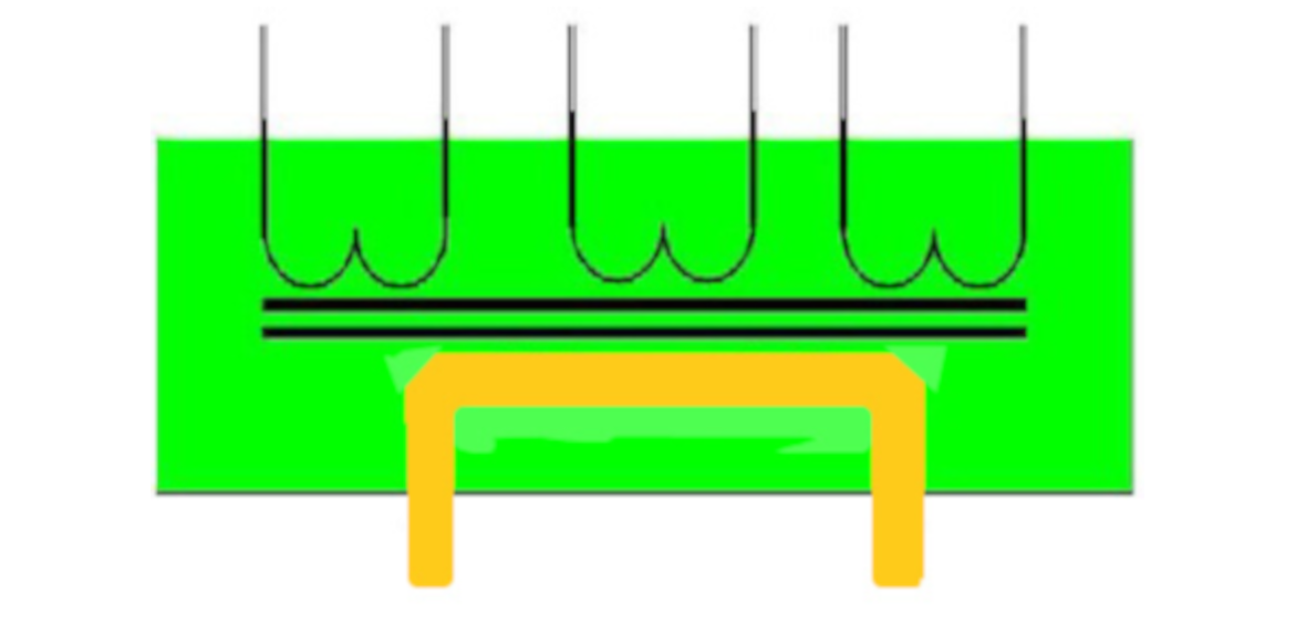
Halfwave Frequency Converter Welding Transformer
Let's assume a phase rotation of A, B, C as shown below. If for example, a weld is performed in period of 3 cycles, the welding control will fire phase A+, B+, C+, A+, B+, C+, A+, B+ and finally C+ for the first weld. On the secondary side of the welding transformer, the inductive impedance is effectively eliminated since current is not alternating during a weld.
The next weld will be performed by reversing the polarity by firing A-, B-, C-, A-, B-, C-, A-, B- and finally C-. Because the core of the transformer is seeing repetitive pulses of similar polarities, the size of the core must be much larger than the 50/60Hz transformer in order to ascertain that the magnetic flux will not saturate during the performance of a weld. It is common to see a 150KVA HWFC transformer the size of one to two cubic meters.
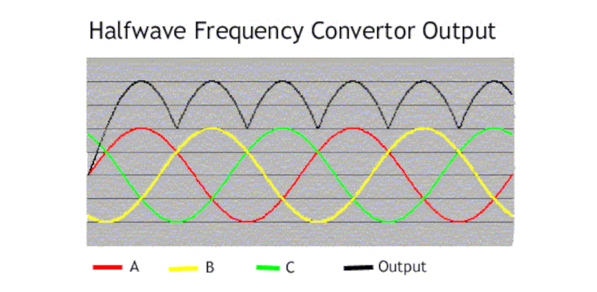
Halfwave Frequency Converter Current Waveform
The welding current appears as shown. The reason why this waveform is called "halfwave" is due to the fact that only positive pulses contribute
for each positive pulse of DC output and only negative pulses contribute for each negative pulse of DC output. Shown here is only a positive
output pulse. As shown, the positive output pulse is derived from A+, B+, and C+.Notice in the output curve shown in black line that there is no inter-cycle cooling periods where the current goes down towards zero. However since this is only half the wave for each pulse, there is significant ripple current at the top of the waveform.